
Back to: Developing Distributed Environmental Sensors
Soldering Connections to the Heltec ESP32 LoRa v2
We are going to add header pins to our Heltech ESP32 LoRa v2 boards so that we can easily prototype our circuit using a breadboard.
Breadboards are have a grid of evenly spaced holes that are electrically connected in either rows or columns. Behind each row/column are two strips of metal that act as springs and will connect to any pins pushed between them, creating a circuit.
Note: new boards can be VERY stiff. Sometimes it’s useful to use a connecting wire or resistor lead first to "loosen it up"/make sure everything is aligned.
We will need 15 header pins, broken into:
- 2 x 1 pins
- 1 x 2 pins
- 1 x 4 pins
- 1 x 7 pins
For groups <3 use a pair of side cutters. Groups larger than ~3 pins you can use two pliers. Breaking by hand also works, but I often end up with one more or less than desired!
The Heltech boards come with two rows of headers, enough for every connection point on the sides of the PCBs. However it is VERY hard to move the screen out of the way without cracking the connector along the edge of glass. I’ve chosen pins that should allow you to solder without having to remove the screen.
If you do want to solder the entire row of headers you can unscrew the screen. Try to pull the screen forward/backwards, keeping it parallel to the PCB. There should be just enough slack in the flex connector to allow room to solder. If you rotate the screen, there is high chance that you will crack the connector where it joins the glass screen- this is from experience 🙁
Once you’ve broken up the header pins you can loosely place them in the breadboard and PCB, using the diagram below as reference. Orient the PCB so the USB connector is close to the left end of the breadboard (this should orient the screen the correct way.) We’ll use the breadboard to mechanically hold everything in place while we solder.
Double check they’re all in the right place.
Noting that there is a connector UNDER the PCB which will not allow you to fully seat the pins and PCB, firmly and evenly press down on the circuit board (NOT THE SCREEN) to seat the pins into the breadboard.
Some of the (single, double) header pins may slip in their plastic holder and not insert into the breadboard. You can fix this by carefully pressing on the protruding end with a pair of fine pliers. You may have to remove it from the board, adjust the location of the plastic and try again.
Now you’re ready to solder!
TIP
Don’t hold the soldering iron on one connection for too long- the heat will transfer through the header pin and melt the bread board.
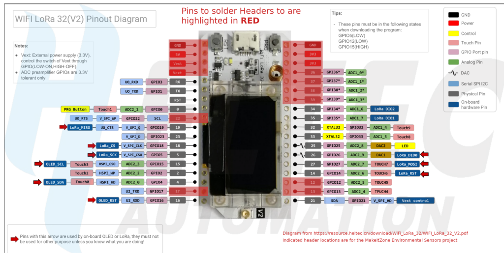
Reference Diagram for the Heltec ESP32 LoRa V2
Soldering Connections for the BME280 Sensor
This one is much easier. Simply snap a set of five header pins and place them in the breadboard horizontally to the right of the ESP32 board. Place the BME280 board onto the pins. You may need to use a small piece of card or similar to make sure it stays flat. Solder the five pins.
